New: Check out our most recent paper on this topic :
S. Depatla, L. Buckland, and Y. Mostofi, "X-Ray Vision with Only WiFi Power
Measurements Using Rytov Wave Models," IEEE Transactions on Vehicular Technology, special issue on Indoor Localization, Tracking, and Mapping, volume 64, issue 4, pp. 1376-1387, April 2015.[pdf][bibtex][Sample data]
Y. Mostofi and P. Sen, "Compressive Cooperative Mapping in Mobile Networks," American Control Conference (ACC), 2009. [pdf][bibtex] (Initial Proposed See-Through Imaging Approach with RSSI Signals)
Y. Mostofi and A. Gonzalez-Ruiz, "Compressive Cooperative Obstacle Mapping in Mobile Networks," invited paper, IEEE Military Communications Conference (Milcom), Oct. 2010. [pdf][bibtex] (First Demonstration of Imaging with WiFi RSSI)
Y. Mostofi, "Compressive Cooperative Sensing and Mapping in Mobile Networks," IEEE Transactions on Mobile Computing, vol. 10, no. 12, pp. 1770-1785, December 2011.[pdf][bibtex] (More Imaging Results with WiFi RSSI)
Y. Mostofi, "Cooperative Wireless-Based Obstacle/Object Mapping and See-Through Capabilities in Robotic Networks," IEEE Transactions on Mobile Computing, DOI: 10.1109/TMC.2012.32, January 2012.[pdf][bibtex] (First Demonstration of See-Through Imaging with WiFi RSSI)
Ph.D. Thesis: A. Gonzalez-Ruiz, "Compressive Cooperative Obstacle Mapping with See-Through Capabilities in Mobile Networks," Dec. 2012.[pdf][bibtex] (Advisee PhD Thesis on See-Through Imaging with WiFi RSSI)
A. Gonzalez-Ruiz and Y. Mostofi, "Cooperative Robotic Structure Mapping Using Wireless Measurements - A Comparison of
Random and Coordinated Sampling Patterns," IEEE Sensors Journal, volume 13, issue 7, April 2013.[pdf][bibtex] (More on See-Through Imaging)
A. Gonzalez-Ruiz, A Ghaffarkhah, and Y. Mostofi, "An Integrated Framework for Obstacle Mapping with See-Through Capabilities using Laser and Wireless Channel Measurements," IEEE Sensors Journal volume 14, issue 1, Jan. 2014.[pdf][bibtex] (Integration of WiFi and Laser Scanner)
S. Depatla, L. Buckland, and Y. Mostofi, "X-Ray Vision with Only WiFi Power
Measurements Using Rytov Wave Models," IEEE Transactions on Vehicular Technology, special issue on Indoor Localization, Tracking, and Mapping, volume 64, issue 4, pp. 1376-1387, April 2015.[pdf][bibtex] ( See-Through Imaging of More Complex Areas)
C.R. Karanam and Y. Mostofi, "3D Through-Wall Imaging with Unmanned Aerial Vehicles Using WiFi," in the proceedings of the 16th ACM/IEEE International Conference on Information Processing in Sensor Networks (IPSN), April 2017.[pdf] ( New paper: First Demonstration of 3D Through-Wall Imaging with WiFi)
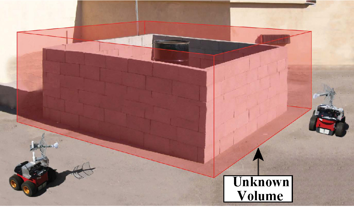
Our proposed approach enables seeing a completely unknown area behind thick walls, only based on wireless measurements using WLAN cards. The figure below shows an example of the considered problem. The superimposed red volume marks the area that is completely unknown to an outside node (such as an unmanned vehicle or a WiFi-enabled smart node) and needs to be seen with details, based on only WiFi measurements. Note that most area is blocked by the first wall, which is concrete and thus highly attenuating. The two unmanned vehicles are interested in fully seeing what is inside at the targeted resolution of 2cm. Note that they know nothing about this area and have not made any prior measurements here.
This figure is generated for illustrative purposes. For a true snapshot of the robots in operation, see our Video and the Sample Imaging Results Section. Note that in the video, any marker on the floor is only for our evaluation purposes and are not used by the robots for positioning, navigation or imaging.
Challenges: This is an extremely challenging multi-disciplinary problem, which involves wireless communications, signal processing, and robotics. Consider the figure above for instance. A horizontal cut of the area of interest is 5.26m x 5.26m. Based on our targeted resolution of 2cm, this amounts to 69,169 unknown variables just for a horizontal cut, resulting in a considerably under-determined system since making that many wireless measurements would simply be prohibitive for the robots. Furthermore, there will be several propagation phenomena that the robots may not be able to include in their modeling. Finally, the robot positioning is also prone to error.
Our Approach:
One robot measures the wireless transmissions of the other robot that is in the broadcast mode. Each wireless transmission passes through the unknown area and the objects attenuate the signal depending on their material properties and locations. By devising a framework based on proper wave propagation modeling and sparse signal processing, we have shown that it is indeed possible for the two unmanned vehicles to image the entire area, with a high targeted resolution, and see through highly-attenuating walls. More specifically, we formulate an approximated wave propagation model. Then, we exploit the sparsity of the map in wavelet, total variations, or space domain in order to solve this severely under-determined system. We have also taken advantage of directional antennas (see the figure above) in order to increase the imaging resolution. See our Video and Related Publications where we introduce our framework, show the underlying tradeoffs of different sparsity/imaging approaches, discuss the impact of different motion patterns of the robots, and present a number of experimental results.
Note that the same approach can be used for imaging on a handheld WiFi-enabled node or on a fixed WiFi network.
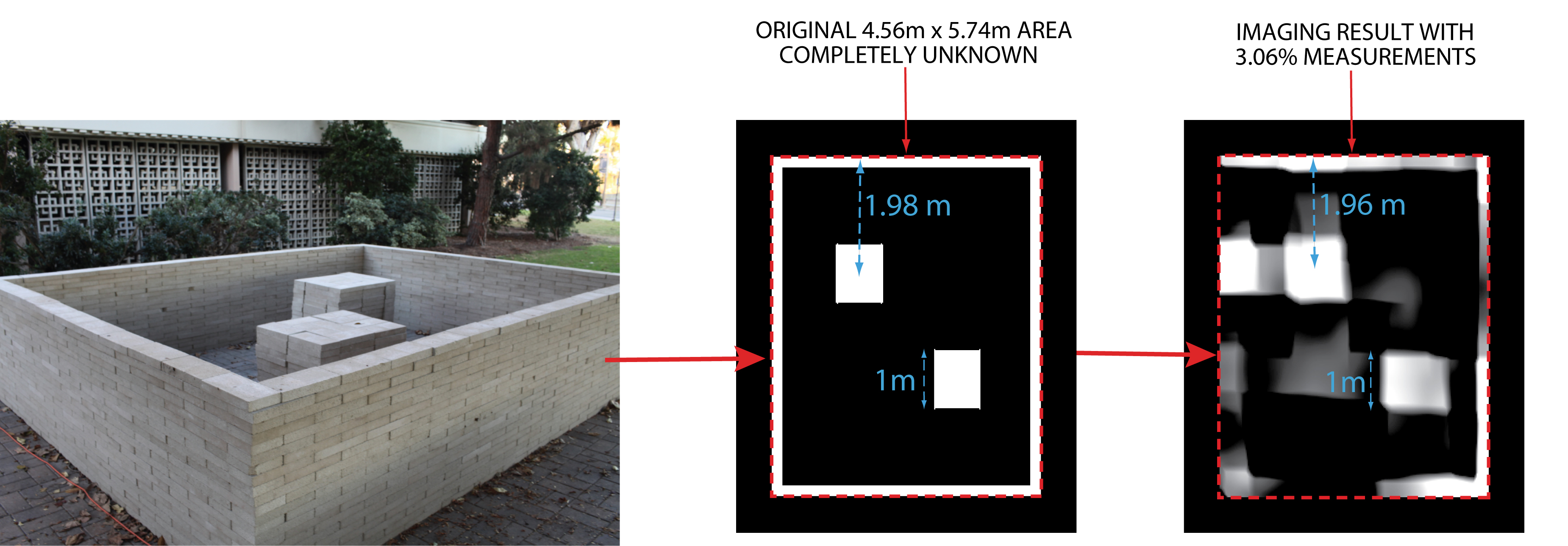
Our initial proposed approach for see-through imaging was published in ACC 2009. Here, we show a few sample results where two unmanned vehicles see a 2D cut of a completely unknown area at the targeted resolution of 2cm. A similar concept can be extended to full 3D imaging. Note that any marker on the ground is only used by us for assessing the accuracy of the operation and is not used by the robots for positioning or imaging. In the imaging results, the quoted percentage measurements denote the percentage of the number of gathered wireless measurements as compared to the total number of unknown pixels that need to be seen. This ratio shows how under-determined the considered problem is. Sample dimensions and their imaged versions are also provided on the figures in blue.
The left figure above shows the area of interest that is completely unknown, while the middle figure shows a horizontal cut of it. The white areas indicate that there is an object while the black areas denote that there is nothing in those spots. Two unmanned vehicles can see through the walls and also see the walls (right figure) based on only WiFi measurements. Check out our TMC Jan. 2012 for First Demonstrations of See-Through Imaging with RSSI Signals and Advisee Ph.D. Thesis 2012 and Sensors Journal April 2013 for more results.
The left figure above shows the area of interest that is completely unknown, while the middle figure shows a horizontal cut of it. The white areas indicate that there is an object while the black areas denote that there is nothing in those spots. Two unmanned vehicles can see through the walls (as shown in the right figure) based on only WiFi measurements. Check out our latest paper in TVT 2015 for the approach that enabled this result.
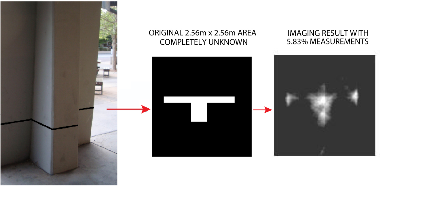
The left figure above shows the area of interest that is completely unknown and needs to be imaged, while the middle figure shows a horizontal cut of it (it is 2.56mx2.56m). The white areas indicate that there is an object while the black areas denote that there is nothing in those spots. Two unmanned vehicles can image this area (as shown in the right figure) based on only WiFi measurements. Check out our Milcom 2010 and TMC 2011 for more details and the First Demonstrations of Imaging with WiFi RSSI.
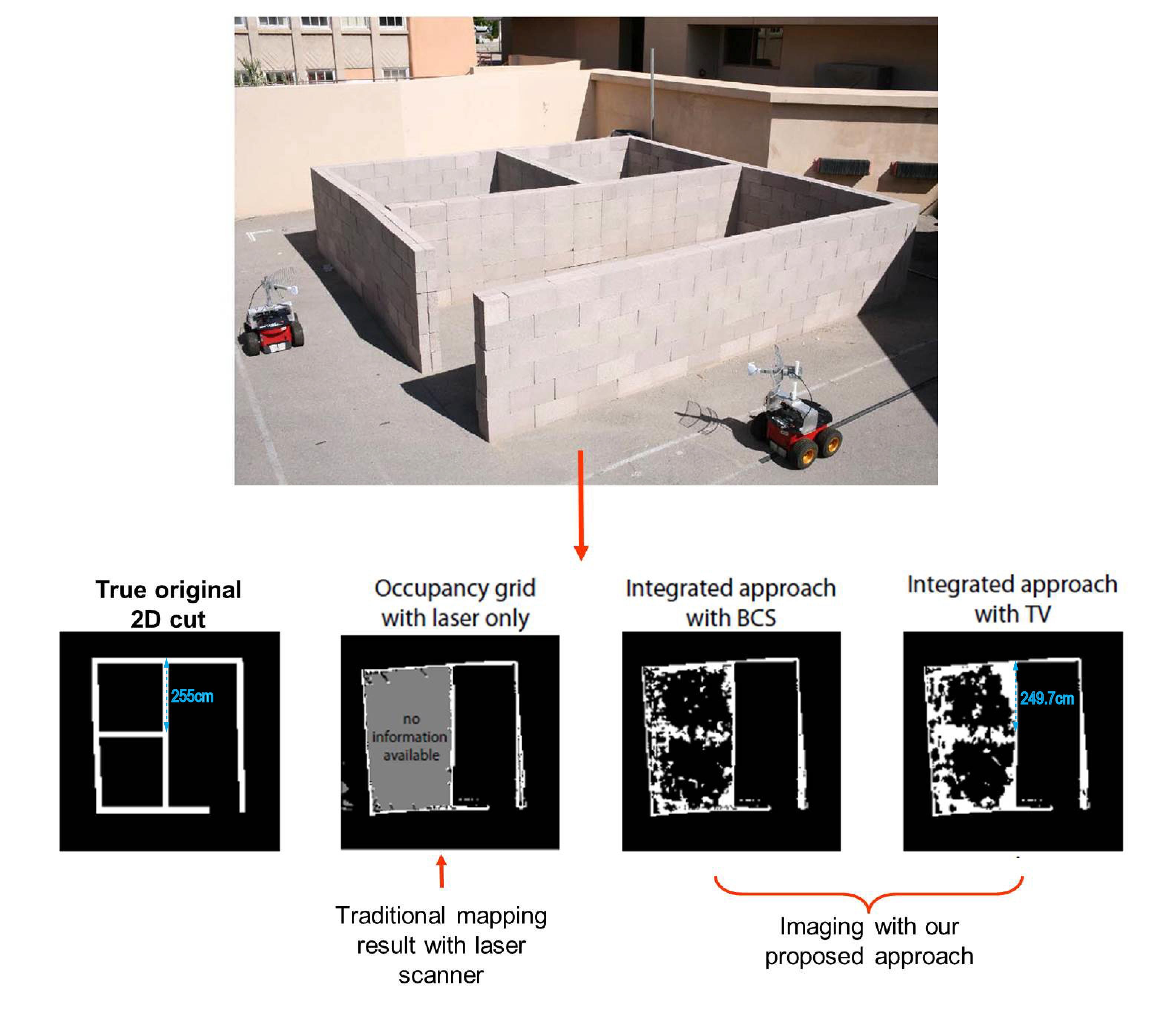
Integration with a Laser Scanner: The figure above shows our proposed integrated framework where both laser scanner and WiFi measurements are used. The first row shows the area of interest that is completely unknown and needs to be imaged, while the first figure of the second row shows a horizontal cut of it (it is 7.67mx7.67m). The white areas indicate that there is an object while the black areas denote that there is nothing in those spots. Two unmanned vehicles then move outside of the area of interest to image a horizontal cut. The second figure of the second row presents the case that only a laser scanner is used. As can be seen, the occluded parts of the structure behind the walls can not be seen, as expected. The two right figures of the second row then show the performance of our proposed integrated framework based on both WiFi measurements and laser scanner data. It can be seen that the details can be clearly identified.Check out our Sensors journal 2014 paper for the approach that enabled this result.
Needed hardware for imaging: Only WLAN card. We have also utilized directional antennas to increase imaging resolution.
Capabilities: Our approach enables seeing a completely-unknown area (with details) through thick walls by using only WiFi signals. This technology can be implemented on any WiFi-enabled gadget. We have furthermore shown how to use this in a robotic setting to give see-through vision to robots. In a typical unmanned vehicle setting, the robots can use laser scanners to see what is in front of them. Clearly, a laser scanner can not see through walls. Here, we have shown that by using only the WiFi measurements, the unmanned vehicles can not only image through walls but can also image the wall itself without any laser scanner. We can additionally integrate our framework with a laser scanner for further capabilities, as is demonstrated in our Sample Imaging Results.
Imaging Resolution: In several of our results, the imaged location of an object (such as its center) is off from its true location by less than 5cm. Sample numbers are provided in our results. Note that we are not just locating a single object but imaging every inch of the unknown space.
Needed Coordination for Taking Measurements in Each Route: None in our latest setup, which allows for faster collection of measurements. The two robots decide on which route to take. Once starting a route, there will be no coordination between the two robots. One robot simply measures its WiFi receptions periodically. The WLAN card of the other robot is in broadcast mode. Each robot keeps estimating its own position and the position of the other robot based on the set speed. Also, each robot traverses each route autonomously in our latest setup. An experiment may consist of a few routes. Once a route is finished, we currently manually move the robots to the start of a new route to save time. This part can be automated as well.
Motion Patterns: We have proposed two different motion patterns for the unmanned vehicles. In what we call "random", the robots (or a robot) have no specific motion pattern and simply walk outside of the area of interest, while measuring the wireless receptions. Note that this does not mean that a random pattern is taken. It simply means no specific pattern is needed. This case is suitable if there are navigational barriers outside of the area, limiting the movements of the robots. In what we call "coordinated", the two robots move in a coordinated (semi-parallel) fashion outside of the area, similar to how CT-scan is done. In this case, the two robots simply decide on which routes to travel before starting to traverse them. Note that they do not have to coordinate their positions (or anything else) as they travel a route and will just set their speeds the same. Each robot then locally estimates its own position and the position of the other robot as it travels its route.
Computational Complexity of Imaging: This depends on the size of the unknown area, number of gathered wireless measurements and the targeted accuracy. Our experience so far has shown less than 100 seconds for processing all the data and getting the image for our biggest structure, on an Intel core i7-3770 at 3.4 GHz.
Onboard Positioning of Each Vehicle: Each unmanned vehicle only has a gyroscope and a wheel encoder for positioning, which are very common parts of unmanned vehicles. This allows it to estimate how much it has travelled in each route and put a position stamp on the wireless measurements it is collecting periodically in that route.
Sources of Errors: Extracting the image information, especially the occluded parts, solely from wireless measurements and with unmanned vehicles is a challenging task due to several sources of errors. For instance, the modeling of the wireless link can not capture all the propagation effects, the problem is severely under-determined, and the onboard positioning of the robot (as well as its prediction of where the other node is) is prone to error. We are thus working on constantly improving our framework to enable the vehicles to image more complex areas.
Search and Rescue, and Surveillance: Imagine a search and rescue operation after an earthquake. The ability to see through walls would allow the outside nodes/humans to assess the situation inside the building before entering it. Furthermore, the automation through utilizing robots would allow the operation to take place in areas hazardous to humans. For instance, consider the nuclear accident after the 2011 Tohoku earthquake and tsunami in Japan. The ability to send unmanned vehicles that can see through blocking objects can tremendously expedite the evaluation of the site from outside.
Occupancy Detection: Our approach can be extended to detect the level of occupancy of an area. This is valuable information for the optimization of several services that depend on how crowded an area is.
Classification of Object Materials Behind the Wall: Our approach can learn the material properties of the objects on the other side of the wall. Thus, it has the potential to classify what kind of objects (human, metal, wood, etc) are present on the other side (in addition to their location and geometry).
Archeological Sites: Having a non-invasive approach to see details through blocking objects, without a need to dig, can be very useful in archeological exploration.
Robotic Networks: The vision of a team of unmanned vehicles deployed in our society to help us with different tasks is closer than ever. These nodes need to constantly build an understanding of their environment (e.g., obstacle mapping) for path planning and navigation. The proposed wireless see-through capability would allow the nodes to cooperatively map areas that have several occluded parts and better plan their trajectories and mission.
Localization for Smart Environments: The proposed see-through wall imaging approach can be deployed on a fixed wireless network or on smart WiFi-enabled gadgets to image hidden objects in an environment. This can increase the capabilities of several location-aware services in future smart homes and malls. Detecting home intruders before entering your house or elderly movement monitoring are a few examples of the possibilities.